Quick and Easy
Standard QA7 Cutting Units
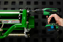
A revolutionary Speed Link system makes it possible to adjust height-of-cut to both sides of the reel in no time. A linking bar connects both sides of the rear roller to a high-reduction ratio worm gear, allowing 1/1000th of an inch adjustments to be made to both sides of the roller simultaneously. QA7 cutting units available in 26-in. or 30-in. widths and 5 or 8-blade configuration.
Easy Service Access
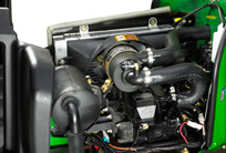
All daily service checks are easily accessible. Simply turn the hood latch and raise the hood to gain service access to the air restriction indicator, engine oil dipstick, backlapping valve, hydraulic components, coolant level fill, and more. The hydraulic tank located at the rear features a convenient fill point on top of the tank and a dipstick for checking the hydraulic fluid level.
Fast, Safe Starting
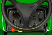
A Sit-on-Seat (SOS) diagnostics system checks the machine system functions to be sure that they are in the proper configuration for starting.
Comfort and Stability
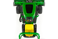
All-day Comfort
2653B PrecisionCut operator platform is designed to maximize operator comfort with plenty of legroom, a ideally positioned steering wheel, and easy-to-reach controls. It's available with a choice of a standard seat movement to provide adjustment for operators of different heights. The deluxe seat also offers seat movement from front to back, and also features lumbar support via an adjustable seat back, armrests, and a suspension system that can be adjusted for different operator weights and comfort levels.
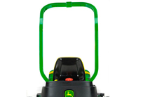
ISO-standard ROPS
A rollover protective structure (ROPS) and retractable seat belt are standard equipment. The ROPS meets pending ISO 21299 standard.
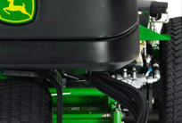
Full-Time 3WD
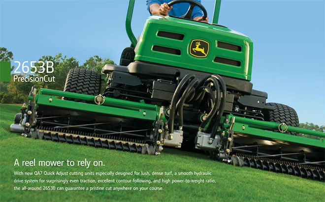
The 2653B PrecisionCut Trim and Surrounds Mower features a full-time 3WD hydrostatic traction system that directs hydrostatic oil flow to wheels with traction in touch terrain. If one wheel begins to slip, the hydrostatic system supplies fluid to the other two wheels to provide traction power. This system also provides plenty of hill-climbing power without the need for extra valves of a weight-transfer system. This reduces the number of potential hydraulic leak points.

Stable Design
A low center of gravity with a wide 55-in. (140-cm) wheelbase ensure comfortable and safer operation even in adverse mowing conditions
Click to visit John Deere website for more info.
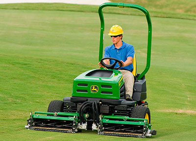
2653B PrecisionCut Key Features
Full-time three-wheel drive (3WD) hydrostatic system directs oil flow to wheels with traction, reducing wheel slip in tough terrain
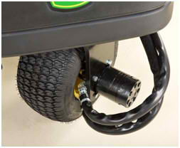
Full-time 3WD system
The 2653B PrecisionCut™ Trim and Surrounds Mower features a full-time 3WD hydrostatic traction system that directs hydrostatic oil flow to wheels with traction in tough terrain. This means if an operator gets into a situation where one wheel begins to slip, the hydrostatic system supplies fluid to the other two wheels to provide traction power.
This system provides plenty of hill-climbing power without the need for any weight-transfer system. What's even more impressive is this system requires no extra valves for operation. This reduces hydraulic leak point opportunities while still providing ample climbing power.
By being a full-time 3WD system, the unit is always in three-wheel drive, even in transport. The system is powered by the same hydrostatic pump used on the 2500B PrecisionCut Riding Greens Mower for optimum hill-climbing performance.
One-piece plenum design, U-shaped hydraulic reservoir, and other conveniences for ease of service
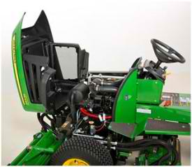
Service access with plenum raised
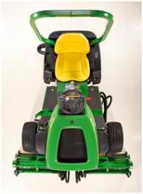
U-shaped hydraulic reservoir
The 2653B PrecisionCut™ makes a strong statement when it comes to service conveniences.
The air plenum and hood are combined into a one-piece design. Simply turn the hood latch and raise the hood to gain service access to the air restriction indicator, engine oil dipstick, backlapping valve, hydraulic components, coolant level fill, and more. All daily service checks are easily accessible.
Standard onboard electrical diagnostics are located beneath the access panel just below the operator control panel. This allows for electrical system diagnosis from the seat. Sit-on-seat (SOS) diagnostics are integrated into the electrical system, alerting the operator to potential starting problems.
The hydraulic oil cooler can be removed by removing wing nuts. The use of wing nuts makes it possible to service the oil cooler without the use of any tools.
A large U-shaped hydraulic tank is easily accessed at the rear of the machine. The reservoir features a convenient fill point on top of the tank and a dipstick for checking the hydraulic fluid level.
The 2653B PrecisionCut Trim and Surrounds Mower features improved access to the engine to hydro coupler for fan belt repair. Simply loosen the locking ring and slide the coupler to allow room for fan belt installation.
Powerful 3-cylinder diesel engine
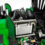
Three-cylinder diesel engine
The 2653B PrecisionCut™ Trim and Surrounds Mower uses a 19.6 hp* (14.6 kW) gross (per SAEJ 1995 at 3000 rpm) liquid-cooled diesel engine for smooth, efficient, and quiet operation.
With the 3-cylinder diesel engine and a large 7.4-U.S. gal. (28.0-L) fuel tank, the 2653B PrecisionCut gives the operator plenty of power and fuel for a productive day of mowing.
This engine meets EPA Tier 2 and Tier 4 compliance standards.
*Engine horsepower and torque information are provided by the engine manufacturer to be used for comparison purposes only. Actual operating horsepower and torque will be less. Refer to the engine manufacturer’s website for additional information.
Durable frame built to handle the toughest terrain
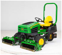
2653B PrecisionCut Trim and Surrounds Mower
The 2653B PrecisionCut™ Trim and Surrounds Mower can improve the appearance of many areas on the golf course. It can maintain tees, approaches, fairways, green surrounds, first-cut rough, and rough. These tough demands can put a strain on lesser frames, but not that of the 2653B Mower.
The 2653B PrecisionCut frame is designed with all these demands in mind and provides excellent weight distribution and the durability required for the most-demanding terrain. The frame design keeps a low center of gravity while providing excellent visibility to the front cutting units and rear of the machine.
Sit-on-seat (SOS) diagnostics provide aid when starting machine
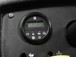
Instrument cluster
SOS diagnostics are provided to assist the operator in getting the machine started. The SOS system checks the machine system functions to be sure they are in the proper configuration for starting.
The system functions that must be satisfied to crank the machine are as follows:
-
Park brake engaged
-
Mow lever disengaged
-
Backlap valve disengaged
-
Forward/reverse pedals in neutral position
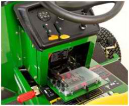
SOS codes
The SOS system alerts the operator by flashing a light on the instrument cluster located on the dash of the 2653B PrecisionCut™ if any these conditions are not met.
The battery indicator light flashes a code while the key is held in the start position. There is a label located on the white box control module access panel that advises the operator what functions are not set properly based on the code that is flashing. This label is in both English and Spanish.
White box electronic control module provides onboard electrical diagnostics as standard equipment
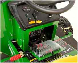
White box controller
This controller gives the technician on-board diagnostics as standard equipment, meaning there are no diagnostic tools or plug-ins to purchase separately. No tools are required to access the white box controller. Simply disengage the latch to open up the access panel. This allows the technician to troubleshoot electrical problems while sitting in the operator seat.
The controller has a heartbeat feature to aid the technician in diagnostics. When the LED light in the center of the controller is flashing at a regular rate, it indicates the controller is properly powered up and there are no circuit problems. Each switch or solenoid on the machine has its own LED light on the controller. Input and output functions can be diagnosed by observing the appropriate lights.
When the heartbeat LED light is flashing at an irregular rate, it indicates there is a system fault of some sort. The irregular flashing rate leads the technician to the circuit to start proper diagnostics. These codes can be found on the front of the access panel to the controller. Detailed information is located in the operator's manual and technical manual.
Frame design for a wide stance and low center of gravity for excellent stability
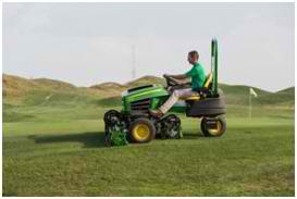
Low center of gravity
A low center of gravity and a wide, 55-in. (140-cm) wheelbase ensure comfortable and safe operation, even in adverse mowing conditions.
Wide 20x10-10 front and 20x10-8 rear turf tires provide excellent traction and stability for superior mowing performance.
Air-restriction indicator with sight glass visually shows if air restriction is present
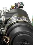
Air-restriction indicator
An air-restriction indicator is standard on the 2653B PrecisionCut™ Trim and Surrounds Mower. The air-restriction indicator has a sight glass with markings that show if service to the air cleaner is required. This air-restriction indicator is the same one used on the 2500B PrecisionCut Diesel Riding Greens Mower.
When the sight glass in the air-restriction indicator shows red, a major airflow restriction in the system needs to be addressed immediately.
Top shield adjustment for clipping dispersal and grass catching

Top shield adjustment
The Quick-Adjust 7 (QA7) cutting unit features an adjustable top shield to either disperse clippings or throw grass deep into the grass catchers. By adjusting the shield closely to the reel, but not touching the reel, the velocity of the grass as it is being ejected from the cutting unit can be increased.
This throws the clippings further out in front of the machine. When mowing without grass catchers, this means better clipping dispersal and recycling of clippings. When mowing with grass catchers, this helps throw grass deeper into the catcher, making sure as many clippings as possible are caught.
The top shield adjustment is an important adjustment that provides for optimum dispersal and catching performance as the reel diameter changes due to wear.
Counter-rotating fairway tender conditioners provide premium flexibility for any maintenance routine
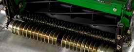
Overall view of FTC
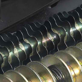
FTC blades
The fairway tender conditioner (FTC) for the Quick-Adjust 7 (QA7) cutting unit is gear driven and counter-rotates to the direction of the reel to stand up grass, for a premium quality of cut.
The counter-rotating blades eliminate clumping by recycling grass clippings for a smooth, clean playing surface. They also groom the turf by slicing stolons on lateral growing grasses, stimulating the plants and promoting new vertical growth.
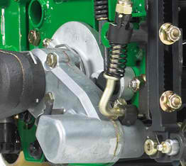
FTC gearcase
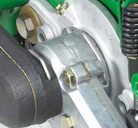
Clip-mounting system
The FTC case is mounted using a simple clip system for quick and easy installation. The gearcase can be used on either side of the cutting unit, meaning the same gearcase is used to drive an FTC driven from the left-hand side of the cutting unit or the right-hand side.
When FTCs are installed with rear roller power brushes, the cutting unit is perfectly balanced by the weight of the rear roller power brush housing. The cutting units can also be perfectly balanced due to a weight system that allows use of the proper counterweight based on the cutting unit width if FTCs are installed without rear roller power brushes.
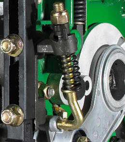
FTC adjuster tower
The FTCs can be adjusted quickly by using a 16-mm wrench or socket to turn a locknut on top of the FTC tower. Turn the locknut clockwise to raise the FTC and counterclockwise to lower the FTC. Each full turn of the locknut changes the FTC height by 0.010 in. (0.254 mm). The system is spring loaded with the spring pulling the FTC away from the turf for optimum performance.
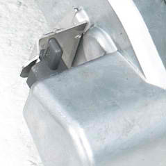
FTC on/off lever
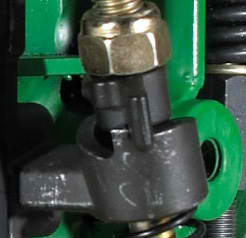
FTC engagement ramp
Due to the gear drive system, the FTC can be turned on or off by rotating a black lever on the side of the gearcase. For times when conditioning the turf is not desired, the FTC can also be moved to a higher height with a T-handle and ramp system.
Simply turn the T-handle up the ramp to raise the FTC and turn down the ramp to lower the FTC into the engaged position. With the FTC in the raised position, a detent at the top of the ramp holds the T-handle and prevents the FTC from moving to the engaged position during use.
Without any tools, the FTC can be rotated into the engaged or disengaged position, or the FTC can be turned off or on, providing ultimate flexibility in how the FTC system can be utilized.
Fixed front roller for less-aggressive attitude at lower heights of cut
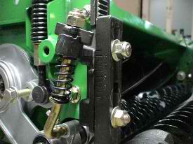
Fixed front roller, notches, and numbering system
To minimize possible damage to the grass plant at lower heights of cut, the Quick-Adjust 7 (QA7) cutting unit features a fixed front roller. If a cutting unit becomes too aggressive, the reel is unable to properly present the grass to the bedknife. This results in an impact cut, similar to a rotary mower, rather than a precise scissor action. A fixed front roller creates a less-aggressive bedknife attitude at lower heights of cut by tucking the bedknife closer to the center point of the reel as the rear roller moves for lower heights of cut.
The front roller uses a notch system to lock both sides of the roller into place. This notch system prevents the front roller from moving during lift and lower cycles, maintaining a more consistent height of cut while mowing. The notches also set the desired height of cut range. Numbers on the roller bracket correspond to height-of-cut ranges in the operator manual. Simply line up the number that represents the desired height-of-cut range with the arrow in the cutting unit casting, and tighten the roller bracket into position. All that is left is to then set the final height of cut by adjusting the rear roller.
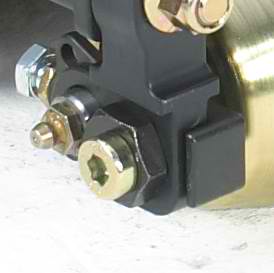
Front roller parallel/eccentric adjustment
The fixed front roller also features a parallel adjustment on each end of the roller. By using a gauge bar, the front roller can be perfectly squared to the bedknife. This ensures the front roller, rear roller, bedknife, and reel are all operating in the same plane, virtually eliminating any chances for step cutting and providing a consistent cutting height across the cutting unit.
An added benefit of the roller bracket design is the brackets are mounted to the front of the cutting-unit housing, so once the front roller is paralleled, there is no need to re-parallel the front roller when moving the roller to a different notch setting.
Belt-driven rear-roller power brush for quiet performance and consistent height of cut
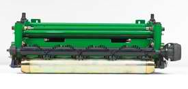
Rear-roller power brush overall
To promote a consistent height of cut, the belt-driven rear-roller power brush prevents debris buildup on the rear roller of the Quick-Adjust 7 (QA7) cutting unit. In some conditions, the rear-roller power brush may also eliminate clumping by evenly distributing grass that may build up on the rear roller. The bristles of the brush are adjusted close to the roller, but do not touch the roller, and rotate when the reel is engaged, deflecting debris off and away from the roller.
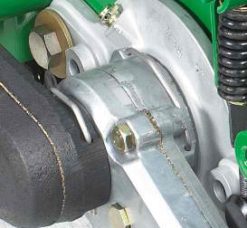
Power-brush clip-mounting system
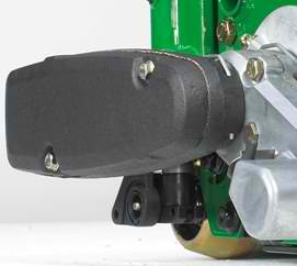
Belt-drive housing
The housing is easily secured to the cutting unit by a clip system. The same clip is used to secure the power-brush housing to the Greens Tender™ conditioner (GTC) gear case if a GTC is installed, or directly to the cutting unit housing if no GTC is installed. The clip system allows a power brush to be installed on the QA7 cutting unit quickly and easily.
For quiet and reliable operation, the power brush is driven by a cogged belt system. To prevent water and other debris from entering the housing, the housing is also sealed by a gasket to prevent damage to the belt or bearings. An innovative cam design is used to quickly set proper belt tension, and also allows for quick and easy brush removal.
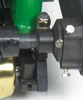
Power-brush adjuster
To aid in speed while adjusting the brush clearance, the system moves in unison with the rear roller so the brush does not have to be readjusted when the height of cut is changed. Only the wear of the bristles over time need to be adjusted; no other adjustment is required.
Two 0.63-in. (16-mm) locknuts on each end of the brush system serve as the adjusting point to set the clearance between the brush and rear roller quickly. All it takes is a 0.63-in. (16-mm) wrench or socket to complete the adjustment. Turn the locknuts counter-clockwise to move the brush away from the roller and clockwise to move the brush closer to the roller.
Notch system for easy and precise reel-to-bedknife adjustments
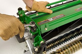
Reel-to-bedknife adjusters on top of cutting unit
The Quick-Adjust 7 (QA7) cutting units feature a quick and easy notch system to maintain proper clearance between the reel and bedknife. The adjustment is performed at each end of the cutting unit for maximum accuracy and precision from side to side. For easy access to the adjustment, the adjusters are located on the top of the cutting unit.
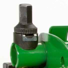
Close-up of reel-to-bedknife adjustment
All it takes to perform the adjustment is one 0.63-in. (16-mm) wrench or socket. As each adjuster tower is turned, each notch can be felt. Each notch represents a reel movement of 0.0005 in. (0.01 mm). This allows for a very fine-tuned adjustment that moves the reel with accuracy and precision. To move the reel closer to the bedknife, turn the adjuster counterclockwise. A clockwise turn moves the reel away from the bedknife.
Simply use the notch system to set the proper reel-to-bedknife clearance of 0.002 in. (0.05 mm), and it is ready to go. This system saves time without sacrificing a premium cut quality for all closely mowed turf areas. Adjustments are so quick and simple they can be performed effectively not only in the shop, but also on the golf course.
An added benefit to the reel-to-bedknife system is that the bedknife is fixed, meaning that when an adjustment is made, the height of cut does not have to be adjusted as a result.
Speed Link™ height-of-cut system adjusts both sides of rear roller at the same time
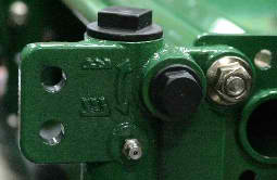
Height-of-cut adjuster
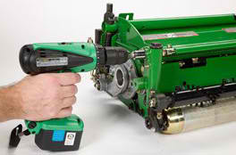
Adjustment with cordless drill
The ultimate in quick and accurate height-of-cut adjustments: The Speed Link height-of-cut adjustment system ties both sides of the rear roller together, allowing technicians to make height-of-cut adjustments simply by adjusting one end of the rear roller.
How does this innovative system accomplish a one-point height-of-cut adjustment? It all starts with the worm gear drives in the rear roller castings. The worm gear system rotates via hex bolts on the side of the rear roller castings, adjusting the rear roller up and down. Simply turn the gears by turning the hex adjuster on the side of the casting; each full turn represents an adjustment of 0.001 in. (0.0254 mm). A diagram on the side of the casting tells which direction to turn the hex bolts to raise or lower the cutting height.
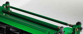
Speed Link system
The true secret to the system is the connecting rod that ties the worm gear systems for each rear roller tower together. With the connecting rod in place, turning the height of cut adjuster on one side automatically turns the other side by the exact same amount. This allows you to adjust the height of cut from one end of the rear roller, making adjustments not only quick but with stunning precision.
The Speed Link connecting rod is also spring loaded, so it can be easily removed should both towers need to be adjusted independently. Once the rear roller is paralleled to the front roller when the cutting unit is initially set up, the Speed Link system takes over and moves each side of the roller by the same amount for a quick one-point height-of-cut adjustment.
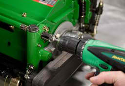
Adjustment with cordless drill
The preferred way to adjust the cutting unit is with a variable-speed electric or air drill with a 16-mm socket attached. Since the entire rear roller can be adjusted from either side of the cutting unit, this allows for adjusting the cutting unit with the most easily accessible height-of-cut adjuster. This takes the challenge out of adjusting the rear cutting units on fairway mowers, riding greens mowers, and trim mowers. A drill makes the adjustment even easier by rotating the tower quickly, making height-of-cut changes a breeze. And the connecting rod ensures the other side turns just as fast and just as accurate.
NOTE: Electric or pneumatic impact tools cannot be used to make the height-of-cut adjustment.
Front and rear roller options to meet virtually any turf condition
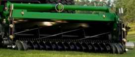
Spiral roller
The 3-in. (76.2-mm) diameter spiral-grooved front roller with spiral end caps allows more grass to stand up along the entire width of the cutting unit, providing a better quality of cut. This roller is also self-cleaning, reduces material buildup on the ends, and improves the overall appearance of the finished cut.
The unique spiral design will not pick up objects commonly found to clog grooved rollers. More importantly, this roller design does not require a scraper due to its self-cleaning design, which works debris to the end of the roller rather than filling the gaps between the grooves. This maintains a consistent height of cut across a wide range of conditions.
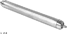
Smooth roller

Grooved roller
Heavy-duty smooth and grooved rollers are available for the front of the reel cutting units.
Heavy-duty smooth rollers are standard equipment for the rear of the reel cutting units.
Both of these roller options have respective roller scraper kits to minimize debris buildup and maintain a consistent effective height of cut.

